How to Create CAD Drawings for Solar, EV Charging & Off-Grid Systems (Standards & Workflows)
The solar industry is growing every passing day. Studies indicate that by 2030, global solar capacity is expected to more than double. IEA studies also state that the U.S. already has over 200,000 public charging ports in operation. Every one of these projects starts with a drawing, a CAD file that defines what gets built and how safely it connects.
Good drafting isn’t glamorous, but it saves projects. When the drawings are right, installers don’t have to guess. Inspectors approve faster. Costs drop. Field crews move without delays. When they’re wrong, even a few misplaced conduits or unlabeled disconnects can throw an entire schedule off.
This guide is for people who make those drawings: CAD drafter, engineers, solar designers, and coordinators who bridge design and construction. You’ll learn real workflows, standards, and tools used in solar, EV charging, and off-grid systems. Besides, we will tell you how to make drawings that actually work in the field, not just look good on a monitor.
Why CAD Drafting Matters in Renewable Energy Projects
Just like construction, renewable energy project management also needs digital plans for ideal execution. A well-formulated CAD draft helps to manage everything effortlessly. Here are the primary reasons why CAD drafting matters in projects like solar panel installation and EV production.
1. Accuracy and Constructability
Renewable systems don’t forgive sloppy drawings. A few inches off on a conduit path, or a mounting hole in the wrong spot, can throw an installation off completely. CAD drawings help prevent that. They show installers exactly what goes where. No guessing, no “fix it in the field.”
Accurate plans save real money. Field errors often cost thousands per project, especially in solar farms or EV charging sites where crews work under tight schedules. In battery-based systems, a misplaced vent or clearance mistake can trigger safety issues or force costly rework.
Key benefits of precise CAD work:
- Less downtime and confusion during installation.
- Better alignment between design intent and field conditions.
- Clear visual coordination for mounting, grounding, and cable routing.
A drawing that’s clear, readable, and accurate becomes a construction map, not just a design reference.
2. Code Compliance and Permitting
Every renewable project lives or dies by code compliance. The National Electrical Code (NEC), IEC standards, and local fire and accessibility rules shape how layouts are drawn. CAD drawings are what inspectors and permitting staff actually review.
When the drawings clearly show disconnects, conductor sizes, rapid shutdown devices, and labeling, approvals move faster. When they don’t, the project stalls. Delays can stretch for weeks while teams revise and resubmit.
In short:
- Solar PV systems follow NEC 690 and related local rules.
- EV charging setups rely on NEC 625 and ADA layout standards.
- Off-grid systems must show safe battery spacing, ventilation, and disconnect access.
Drawings aren’t just paperwork. They’re a form of communication between the engineer, the installer, and the authority that decides whether your design can be built.
3. Interdisciplinary Coordination
Renewable projects sit at the intersection of several trades. These include electrical, civil, structural, and sometimes architectural. Each one touches the same site differently. CAD is what lets them work together without chaos.
For example:
- The structural team places roof anchors for PV racks.
- The electrical designer runs conduit and labels disconnects.
- The civil engineer handles grading and trench routing.
Without shared drawings, these worlds collide. CAD keeps everyone aligned through shared layers, clear references, and updated base models. When something shifts (a conduit path moves or an inverter pad changes size) the updates flow through to all teams. That’s what prevents “clash detection” moments in the field that can cost days to fix.
4. Speed and Scalability
Most renewable design firms don’t work on one project at a time. They might be designing twenty rooftop systems or several EV charging lots across different states. Standardized CAD templates and workflows make that possible.
A few reasons this matters:
- Using predefined layers and symbols saves hours on each drawing set.
- Once a layout works for one site, it can be adapted for another with minimal change.
- Revisions happen faster. For instance, a change in racking tilt or pad layout takes minutes.
Consistency builds speed. Teams learn the system once and replicate it without reinventing the drawing each time. That’s what lets large programs (like statewide EV charger rollouts) move from concept to construction without bogging down in drafting.
Key Standards & Codes Every CAD Drafter Must Know
If you’re doing CAD work for renewable systems (solar PV, EV chargers, or off-grid battery setups), you already know the hard part isn’t drawing lines. It’s proving that what’s on paper can be built, inspected, and signed off without anyone raising a flag. Every circuit, disconnect, and pathway you show lives under a set of electrical and safety codes that dictate how it needs to look. Get them wrong, and you’ll spend your next week redlining.
Let’s go system by system.
Solar PV Systems
- NEC Article 690: The solar bible in the U.S. It tells you where to place disconnects, how to label modules, how far a rapid shutdown device should sit, and what counts as “readily accessible.”
- IEC 60364-7-712: If you ever work on international or export projects, this covers similar ground for low-voltage PV systems.
- Local building and fire codes: These sneak up on you. They’ll define how close panels can sit to a ridge, how much roof space must stay open for firefighters, and how you show roof load or penetrations.
How It Shows Up in Drawings
You can spot a solid solar drafter by looking at their plan sets. They show:
- Disconnects are labeled right where an inspector expects them, not buried in a note somewhere.
- Inverters tagged, voltage ratings listed, breaker sizes next to feeder lines.
- Grounding paths are drawn on their own layer, so anyone can trace them from the array frame to the electrode without guessing.
- Fire setbacks are drawn as dashed lines on roof plans, often thirty-six inches between module groups or near the eave.
- Roof attachments are detailed properly. These are not just “typical” notes but actual callouts showing flashing, sealant, and structure below.
Every line you place here is about traceability. Someone on a roof, usually in 110-degree heat, will follow that drawing.
EV Charging Systems
- NEC Article 625: This is the one governing electric vehicle charging installations. It defines continuous load ratings, conductor sizing, and disconnect rules.
- IEC 61851: You’ll see it on international projects for conductive charging systems.
- ADA accessibility and site layout rules: These dictate where chargers go, how wide access aisles need to be, and what signage must appear.
How to Draft for It
EV charger drawings live halfway between electrical and civil work. You need to think about trenches, traffic flow, bollards, and conduit just as much as voltage drops.
In CAD terms:
- Feeders should trace from the panelboard to the charger base with clear labels for conduit type, size, and route.
- Mounting pads aren’t generic rectangles. These show pad thickness, rebar, and the stub-ups for conduits.
- Label your accessible stalls. Add the striped aisle next to it. Don’t forget the 5-foot access zone or the sign height. Inspectors love catching that one.
- If you have multiple chargers, label each one: “EV-01,” “EV-02,” etc. and tag corresponding disconnects.
- Include trench depth notes, sleeve locations under pavement, and protective bollards if vehicles might back into the charger.
In short, make it obvious enough that a field crew could build it without calling you for clarification.
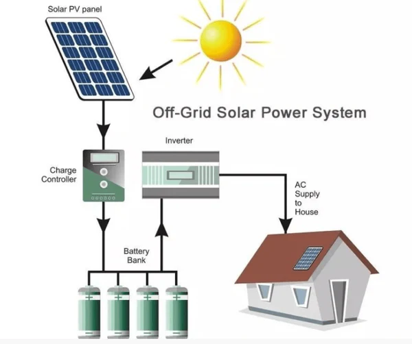
Off-Grid & Battery Storage Systems
- NFPA 855: Governs how stationary energy storage systems are installed. Think spacing, ventilation, fire separation, and hazard labeling.
- NEC Article 480: Covers electrical connections, overcurrent protection, and grounding for storage batteries.
- International Fire Code (IFC) 1207: Deals with fire-rated construction, battery chemistries, and emergency access for ESS rooms.
How It Should Look in Drawings
Battery systems are where detail saves lives. The room layout should tell you everything without reading a single note.
Include:
- Battery rack spacing. Mark clear aisles (three feet minimum is common). Label each rack by type and chemistry: lithium-ion, lead-acid, whatever’s there.
- Ventilation flow. Show arrows for intake and exhaust, fan symbols with CFM callouts. If there’s a mechanical schedule, cross-reference it.
- Grounding and bonding. Use one continuous path to a grounding electrode, drawn in full, not assumed.
- Structural anchoring. Indicate pad foundations, anchor bolts, and seismic restraints where required.
- Fire separation. If the room has a rated wall, show the hatch pattern or line type. Label egress doors with width and swing direction.
| System Type | Primary Standards | What You Must Show | Typical Drawing Sheets |
| Solar PV | NEC 690, IEC 60364-7-712, Local Fire Codes | Disconnects, grounding, fire access, racking details | Site plan, array layout, one-line diagram, detail sheets |
| EV Charging | NEC 625, IEC 61851, ADA Accessibility | Feeder routes, pads, accessibility zones, signage | Electrical plan, trench section, site layout |
| Off-Grid / Battery | NFPA 855, NEC 480, IFC 1207 | Battery spacing, ventilation, grounding, fire safety | Battery room plan, elevation, safety notes |
Solar PV CAD Drafting Workflow
You can’t shortcut a solar drawing. It’s not just lines on paper but the entire story of how sunlight turns into power and how that power moves safely through real equipment. Each phase of drafting stacks on the last, and the clearer you make it, the fewer surprises happen in the field. Besides the CAD drawing, help estimate residential electrical projects. Here’s a complete workflow for your assessment:
Site Survey & Data Collection
This part gets overlooked all the time, but it’s where good drawings start. If your base plan is wrong, everything else (tilt angles, racking positions, conduit runs) falls apart later.
Before anything else, gather the real site data. Not just the pretty aerial image. You need:
- A topographic survey with spot elevations and contours.
- Roof pitch, azimuth, and slope direction (a few degrees off can ruin a string layout).
- Obstructions like vents, skylights, parapets, and mechanical units.
- Structural load ratings or existing truss data.
- Utility service entrance and main panel location.
If you can get a DWG from a licensed surveyor, use that. If not, build your base geometry from a point cloud or a drone scan. Revit site models are great too — especially for multi-building campuses where everything connects.
Drawings that start with bad geometry always cause field headaches. A crooked ridge line, a missing roof drain — these things force last-minute redesigns that cost real money. Double-check everything before you start laying panels.
Conceptual Layout & Array Arrangement
This is where you shape the actual array with rows, orientation, spacing, and all the physical constraints.
Start by locking in module orientation. Landscape, portrait, or mixed? That decision affects everything from wiring length to conduit routing. Then, lay out your grid using accurate module dimensions, factoring in clamps or spacing between panels.
Now bring in fire setbacks and access pathways. Most jurisdictions need 36-inch aisles between module groups and at least 18 inches from roof edges or ridges. Don’t guess — check your local code and fire department spec.
Use simple layers for this part:
- PV-ARRAY for modules
- PV-ACCESS for pathways
- PV-SETBACK for clearances
Shading is another hidden killer. Even a vent pipe can wipe out production if it’s in the wrong spot. Run a quick shade study or overlay obstructions on your array. If you’re using tools like Helioscope or PVsyst, export your shading layout into CAD and snap your modules to real sunlight data.
Once the pattern feels solid, mark your stringing zones. Annotate how many modules per string and label section IDs like ARRAY-A1, ARRAY-B2, etc. Add notes for tilt, azimuth, and any module spacing changes.
Structural Attachment & Racking Details
This is where design meets physics. Every attachment detail must hold up under wind, snow, and seismic loads.
Start by identifying anchoring points on the structure. For roof-mount systems, show where each stanchion or clamp attaches to the rafter or deck. Don’t rely on generic callouts like “anchor per manufacturer.” That’s a red flag for reviewers. Instead, show actual spacing and pattern.
If you’re drafting a ground-mount, use clear symbols for piers or driven posts. You can also use simple electrical takeoff software to ensure accuracy. Also, label dimensions between rows and include pier embedment depth in your section details. Always add waterproofing and flashing details.
Electrical One-Line & Single-Line Diagrams
This sheet is where electrical inspectors focus most of their attention. It’s also the part that separates solid drafters from messy ones.
The hierarchy should be clear at a glance:
Modules → Combiners → Inverters → Disconnects → Utility
For every component, show labels and ratings.
- Voltage per string and array.
- Breaker sizes.
- Conductor types and insulation ratings.
- Grounding conductors.
- Overcurrent protection devices.
Keep the linework consistent. AC and DC circuits should look different. Many drafters use dashed lines for DC, solid for AC. Whatever you pick, keep it uniform.
Tag every piece of equipment. Inverters as INV-01, disconnects as DISC-02, etc. Reference those same tags on your plan view so everything ties together.
Don’t forget code notes. NEC 690.7 for voltage limits, 690.8 for current calculations, 690.43 for grounding. Put those right on the sheet where they apply, not buried in a general note block. It shows reviewers you know what you’re doing.
And most importantly, make the flow logical. Anyone should be able to start at the array and trace power all the way to the utility meter without getting lost.
Call Us To Get Ideal Cost Estimates For Solar PV
Conduit, Cable Tray & Equipment Plan Views
Now comes the coordination part. Lay out your conduit runs carefully. Use smooth routes that avoid excessive bends. If you can, show the conduit in plan and in section. Draw parallel runs with spacing notes
If you’re working with a 3D model, check your conduits against roof drains, skylight curbs, and parapet heights. Nothing slows construction faster than a conduit path that collides with an existing pipe.
When showing equipment placement, include dimensions from walls, roof edges, and other utilities. Leave working clearances per NEC 110.26 (usually 36 inches in front of electrical gear).
A few small details make big differences:
- Label conduit size (EMT ¾”, PVC 1″, etc.).
- Note whether it’s rooftop, underground, or interior.
- Add slope arrows for rooftop conduits to drain water away from boxes.
If there are cable trays or wireways, mark their support spacing and elevation. Reviewers like seeing that level of thought. It proves your layout wasn’t random.
Elevations, Sections & Detail Sheets
Include racking elevations showing module tilt, clearance from roof surface, and overall height. Add notes like “MODULE TILT = 10° SOUTH” or “TOP OF ARRAY = 4′-8″ ABOVE ROOF.”
Show sections through typical module rows, especially where conduits drop through the roof or where racking transitions between levels. Call out all relevant layers: roof membrane, insulation, structure, flashing, sealant.
For ground-mounts, draw at least one full section showing pier foundation, cable trench, and fence line if applicable. Include ground clearance and module edge height for shading analysis verification.
Add detail sheets for key components: racking, inverter pads, disconnect mounting, and labeling. Label everything in plain language. A note like “SEE DETAIL 3/A-501 FOR ROOF ATTACHMENT” saves confusion later.
Every installer and inspector looks for something different on these sheets. The clearer they are, the smoother the job goes.
As-Built & Handover Deliverables
As-built drawings aren’t just a formality. They’re what operations and maintenance teams rely on years later when something fails.
After installation:
- Update your stringing to match what was actually built.
- Tag every inverter, combiner, and disconnect with final ID numbers.
- Mark conduit routes and sizes as installed.
- Add final equipment submittals or datasheet references if they differ from the design set.
- Track every revision in a small table (date, description, initials).
Once that’s done, compile your handover set:
- PDF drawing set with revision history.
- DWG or Revit model, if required by the client.
- Panel layout with stringing table.
- One-line diagram reflecting as-built conditions.
- Equipment list with manufacturer, model, and serial.
FAQs
What CAD drawings are needed for a solar permit?
Usually, a site plan, roof or array layout, and an electrical single-line diagram. Add racking details, labels, and equipment specs. Some cities also want fire setbacks or load calcs.
How do you draft a PV single-line diagram?
Begin with modules, move downstream to combiners, inverters, and the utility tie-in. Keep conductor paths clear, label voltages, and note protection devices. Inspectors want to see logic, not art.
What standards govern EV charger drawings?
NEC Article 625 defines wiring and protection. ADA rules control parking and access space. Local codes vary. So, always verify conduit depth, signage placement, and bollard spacing before finalizing any layout.
How do you design a battery room layout in CAD?
Show rack spacing, ventilation paths, and exits. Label equipment, airflow, and fire barriers. Keep aisles at least three feet wide. Clarity here isn’t just aesthetic but a safety issue.
Is AutoCAD or Revit better for solar design?
For small sites, AutoCAD is faster and lighter. Revit shines on large or multi-trade projects needing 3D coordination. Many firms use both: CAD for permits, BIM for construction and coordination.
What are common CAD drafting mistakes in renewable projects?
Missed clearances, wrong breaker sizes, outdated notes, uncoordinated conduit runs, and mislabeled strings. Most errors start from copying old templates without reviewing against the current code. Always double-check early.
How do you prepare as-built drawings for solar systems?
Update the approved set after installation. Revise stringing, conduit paths, and labels to match field conditions. Add serials and date the sheet. The as-built becomes the real system record.
Conclusion
CAD and BIM drafting sit quietly behind every renewable system that actually works. Good drawings cut confusion, reduce rework, and make inspections almost painless. Codes keep shifting, so stay updated with templates, symbols, layer names, all of it. Train your team. Talk to installers. Draw like someone’s building it in 100-degree heat. The difference between a smooth project and a nightmare is usually one clear line on a plan. Keep refining your workflow, and your drawings will speak for themselves long after the project’s done.
